…. by using an extra ferrite for less than 20 cent
… you can skip the technical details and go to the solution at the end immediately
I bought two CMOD A7 boards with a Xilinx Artix-7 35T to test interconnection of two soft RISC-V cores. Btw. the Artix7 is one of the best FPGAs out there. Great job Xilinx.
These boards have a USB to JTAG interface for debugging and uploading bit streams to the FPGA. Power for the board can be delivered over this connection too.But I ran into serios USB problems while playing around with these boards.
The first board was working ok most of the time, but the second board lost connection to USB all the time. Especially while using JTAG for debugging.
While looking for a solution I found many forum posts about this issue
https://forums.xilinx.com/t5/FPGA-Configuration/Problem-with-Cmod-A7-JTAG/td-p/792624
https://forum.digilentinc.com/topic/18024-defective-jtag-on-digilent-cmod-a7-35t-board/
https://forum.digilentinc.com/topic/4769-vivado-hardware-manager-disconnects-cmod-a7-target-in-win7/
https://forum.digilentinc.com/topic/17435-unstable-usb-connection-with-cmod-a7-35t/
https://forum.digilentinc.com/topic/9766-digilent-cmod-a7-disconnects-andor-does-not-program/
The manufacturer advised to use a better cable. But every cable I tried was not working.
Let us have a closer look at the hardware
This is a picture from the reference manual for the power stage:

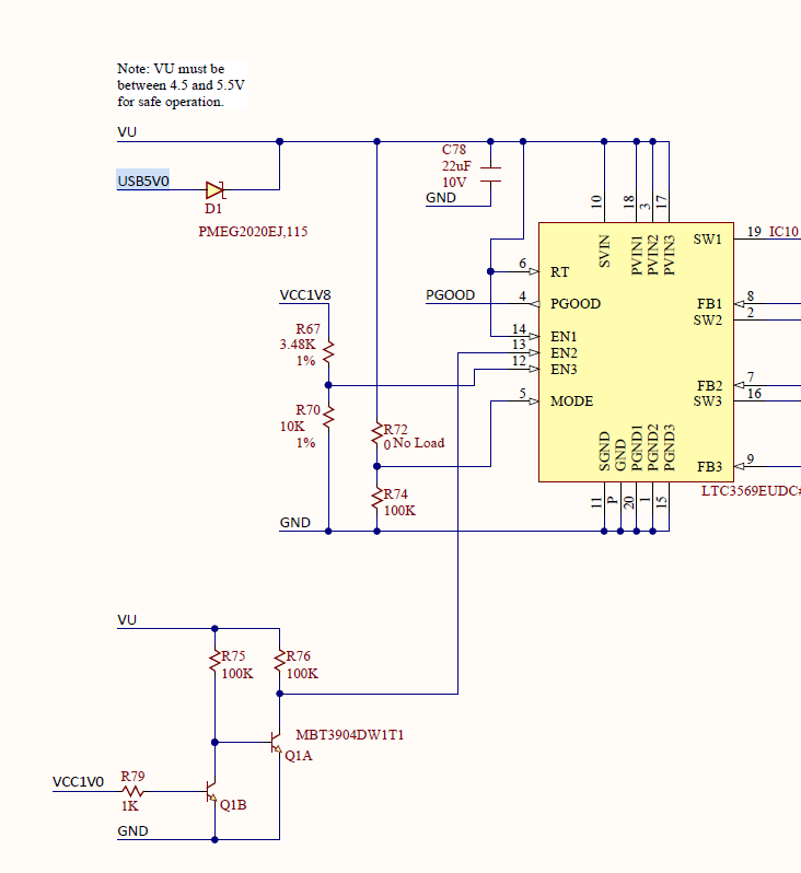
The board allows two power sources to be connected. To avoid current flowing to the USB host the designers added a little Shotkey Diode if both sources are connected.
Here is the schematic for this part

At first glance this is looking decent. Unfortunately, the USB data line part is missing in the CMOD A7 schematics. But let us be honest, design flaws would be hard to fix there.
The better way seems to focus on the power part.
Best way to start here is a little frequency analysis 😊 Measured above the usb connector.
What we are seeing here is a high noise floor coupling into the usb cable. Especially around 2.2MHz. My first guess was that this might be related to the burst mode of buck regulator. Mostly USB disconnects under load. Most time when using Xilinx chipscope.
Solution
The weapon of choice for noisy power lines is usually a little ferrite bead. And the good news is a SMD ferrite bead is easy to install here.
Be careful: Do not connect two power sources at the same time after replacing the diode.
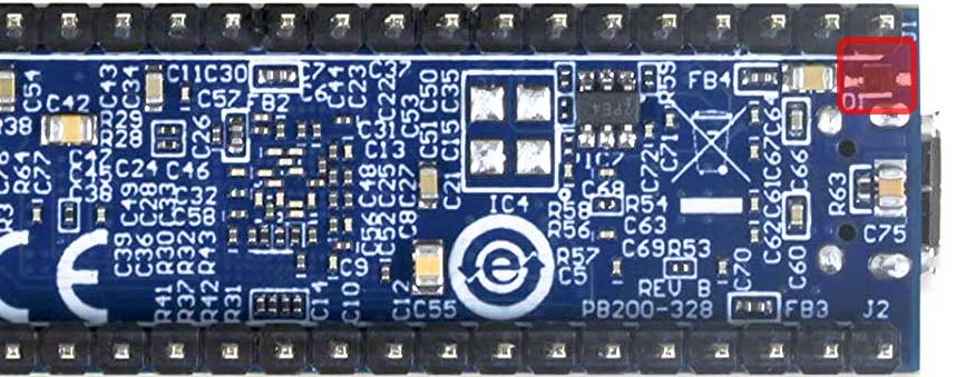
We just replace the diode with a ferrite bead.

I use this one: Wurth Elektronik part number: 742792037
But you can use any ferrite with similar values
Here you see the result after replacing the diode with a ferrite 😀
The result:
No more connections losses! I tried the worst cables I could find. Not even one failed.
Resources:
[1] Measuring with Modern Spectrum Analyzers Educational Note
[2] WE-CBF SMT EMI Suppression Ferrite Bead ORDER CODE 742792037
soldering took a while. finally can use it
I tried the capacitor solution the developers provided in one forum post without success. This finally fixes the problem.
They are so many posts about this issue. Why is not fixed by digilent :’( The company is just shit.
Do not be to harsh. The overall design of the board is really descent. SRAM / FPGA and flash memory are running flawlessly.
I use this ferrite: BBPY00201209331Y00
THANK YOU!!! We have more than 150 of these boards in field. Our service techs could not update them with their laptops.
I made a little USB to USB adapter board with a SMD ferrite (I used another one but with similar values) and now it works!
You can’t image the struggle we had. Usually, I don’t comment anything online but this time I had to.
thumbs up!
Can confirm. Works for me.
Yes!
Wie repariere ich eine Shimano-8-Gang-Fahrradschaltung?
Thanks for sharing the frequency analysis, could you please let me know what equipment you use to perform the measurements?
Data was post processed by means of Python and Matplotlib?
Thanks.